
(11) Railway: free-standing or automatic with 9825 — DX and FX P82 instructions initiated and managed by the HP-9825, connected via the remote (R3) connector. Remote (R1) connected to the screen and curtains and initiated optical coupled spotlight fader circuits located above the screen. Remote (R2) connected the control circuitry of the Leslie speed mechanics plus Hammond B3 audio signals for playback and record. ProjA&B linked the remote projector circuits but no long cable needed as the P82 and the projectors were mounted in the same rack.
The attic room, like all floors of the house, was made of concrete — so empty tubes for the cables had been foreseen as part of the construction, as was the location of all room light switching to allow connection to P82. See plan below.
Index — P82: archive post — P82 build — revival(a) — revival(b) — revival(c) — remote (d)

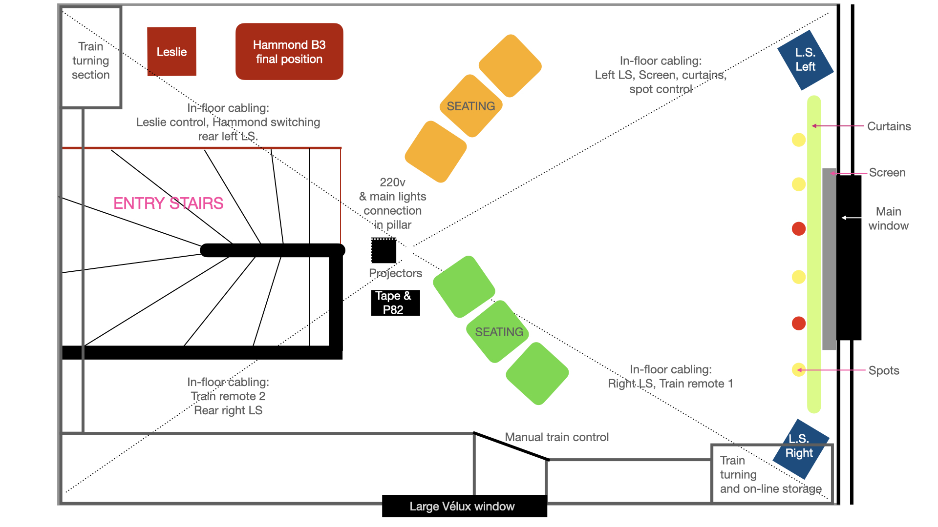
Physical position of the railway layout within the attic room:
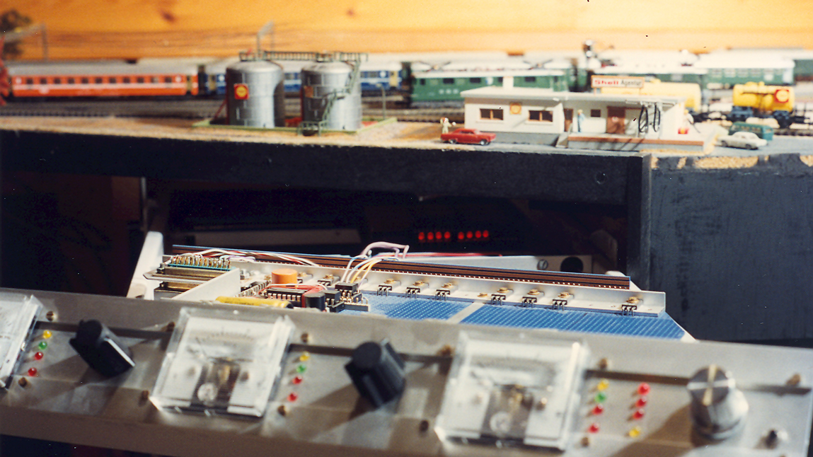
Views of the layout along the main viewing section We are unable to physically revive the railway section as the whole layout was eliminated when moving out of the house in 2004 — part of the ‘spaceship’ exists no more! Most of the remote circuitry remains, yet with no trains and no track we can but reminisce. Remote circuits (R3) for the train were the last to be designed and built, towards the latter half of the 1980’s and although enough of it was working to prove design concepts and viability, lack of time and focus inhibited completing the big plan (!)
In fact, to reduce complexity of programming train movement, some areas were controlled by independent hardware requiring simple commands and track detectors. Thus as example, the train turning sections could receive a moving train and take charge of it by bringing it to a halt in an empty storage track until receiving request to bring it out again. These sections had their own locomotive power and turnout activation dedicated to that simple functionality. All motion took place “behind the scenes” so no scale motion was needed – it worked pretty well.
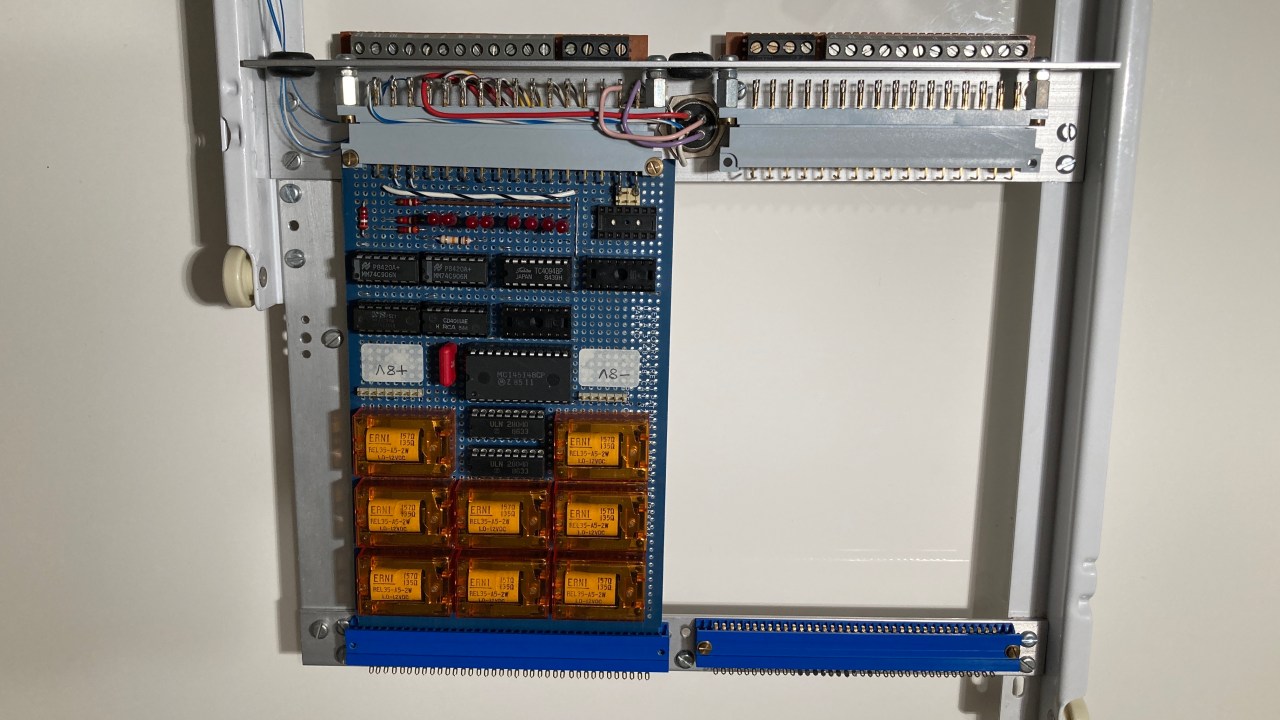
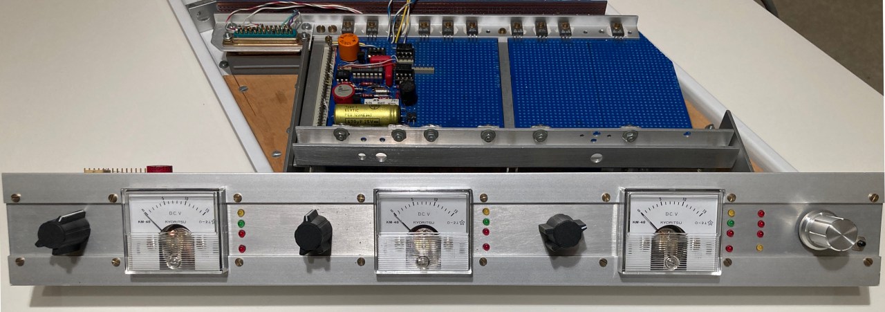
For the visible part of the “show”, we were well into the process of connecting turnout motors and signal lamps and having track detectors at critical places, it was working well, a great pleasure, so close to our vision, but not yet reaching the intended complexity of automatic train movements. From the electrical and electronic circuitry side, all was complete and ready to receive the track connections – many relays, substantial power supply, and programmable motion control matched to any specific locomotive (because there is a significant response difference between models).
Model railway – more circuit details in search of reliability and realism.
Remote circuits were all part of a model railway where train movement, route selection and signalisation could be controlled manually or programmed by the HP9825 computer working through the main P82 control unit — to send commands and to receive real time status back. Such status could be handled either through interrupt or by regular poling – typical example would be: make a train start, change the signals, clear the way via turnouts, check where the train is, stop it at the right place and with a decent scale deceleration by means of pulsed power with characteristics matched to the locomotive.
One major physical problem with the small size of “n” gauge, is non-contact with the rails because of dust or other contaminant. We have experimented with having a truck or carriage next to the locomotive containing a battery to provide temporary voltage whenever there is no pulsing detected through the normal pick-up. The principle assertion being that the convoy always moves forward until it finds contact.
Practical considerations:
1. All tracks must be fed with an “idle mode” pulse which is detected to disable the battery, but below the level which would activate the motor.

2. Connecting wire between the battery wagon and the locomotive can cause derailment. Ones in this photo are too big, too rigid, and too visible.
3. The battery system is for forward motion only – it must be disabled during manual reverse operation, which thus cannot be part of an automatic “show”.


Index — P82: archive post — P82 build — revival(a) — revival(b) — revival(c) — remote (d)
