
(10) P82 back to life . . . many techy details.
Index — P82: archive post — P82 build — revival(a) — revival(b) — revival(c) — remote (d)
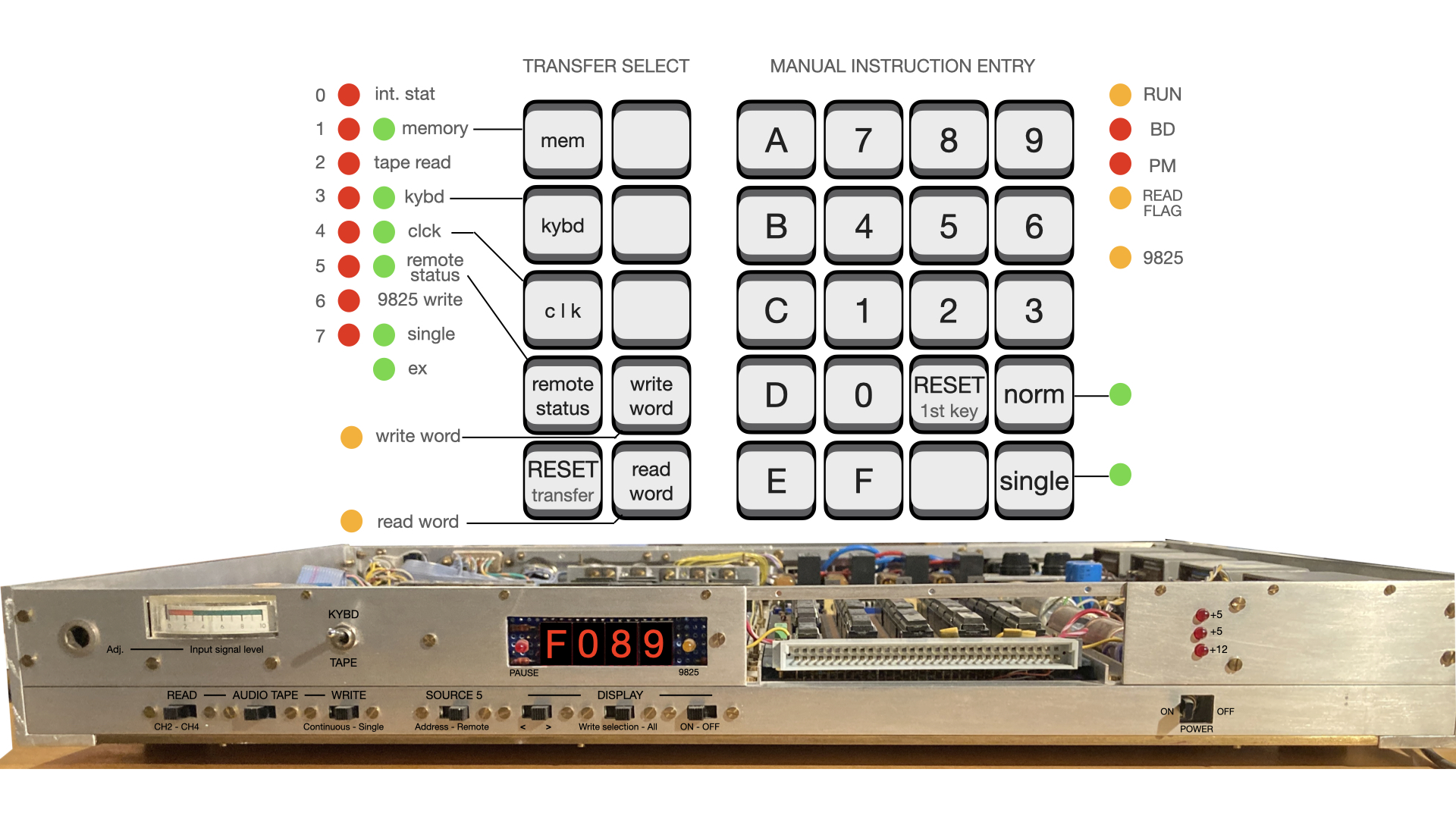
MEMORY
No core memory as was in the AGC, same capacity using a single chip CMOS static RAM — yet a distinct downgrade as content is lost when power goes down.
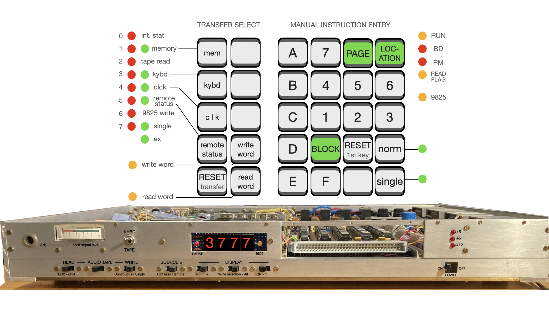
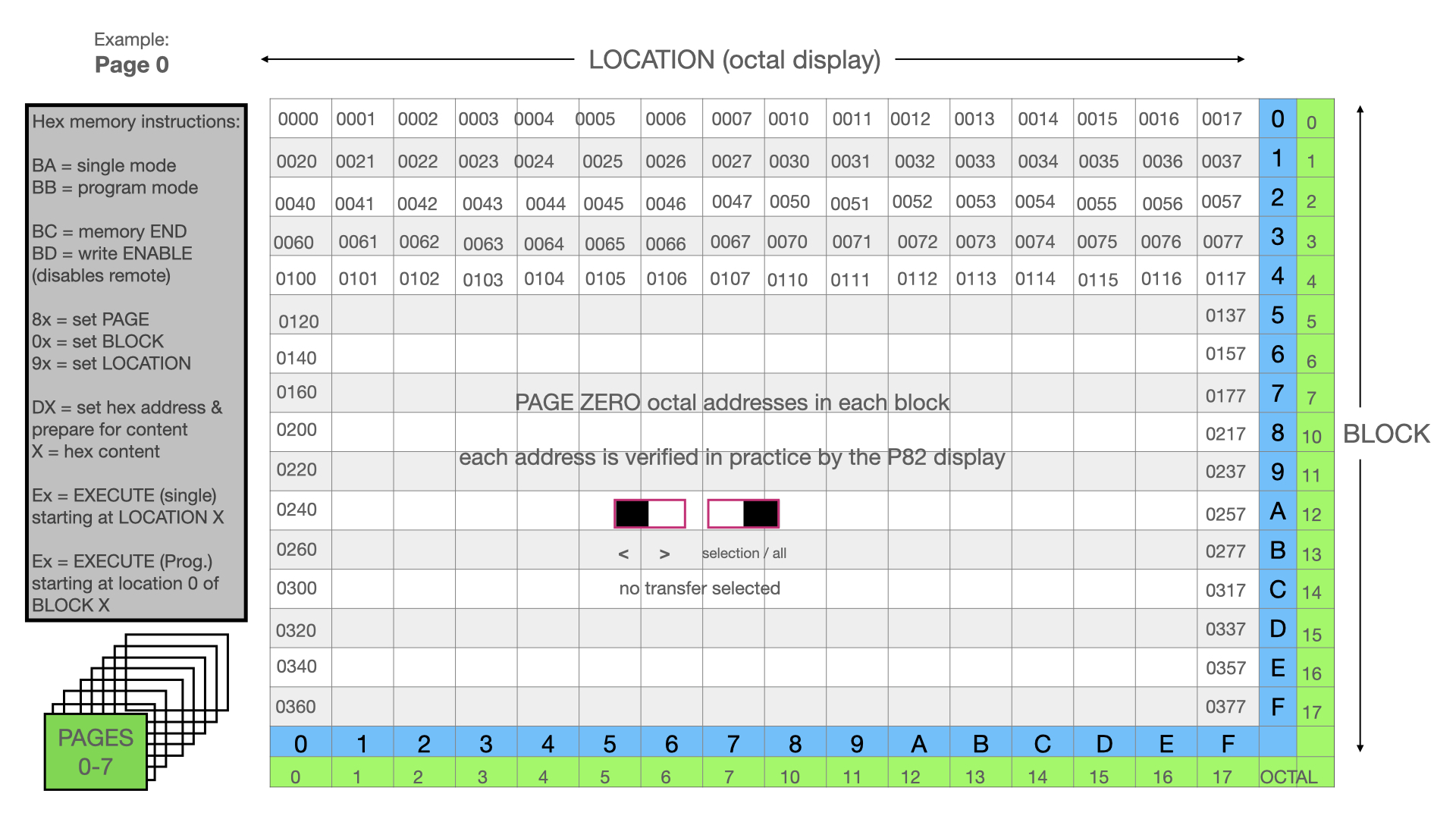
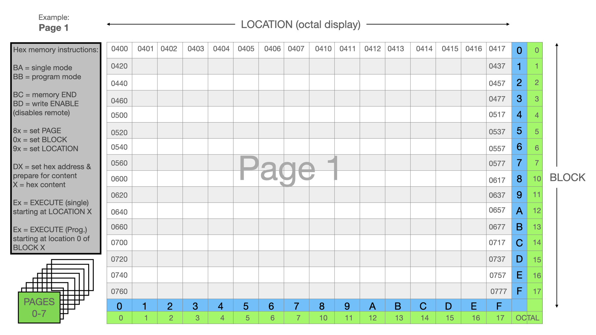
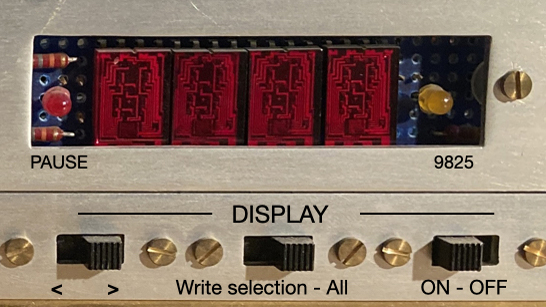
Originally this 16384-bit (2048x8bits) memory was loaded using the HP9825 or short sequences from the keyboard. Our current tests remain keyboard initiated, focusing on the independent, free-standing operation of the P82. The design defined memory access by 8 pages of 16 blocks by 16 locations. There are some quirks for manual operation in that the displayed addresses are in octal while the keyboard input is in hexadecimal – this took some time to sort out via experimentation and our logic diagrams which are fortunately very good!

INSTRUCTION SET
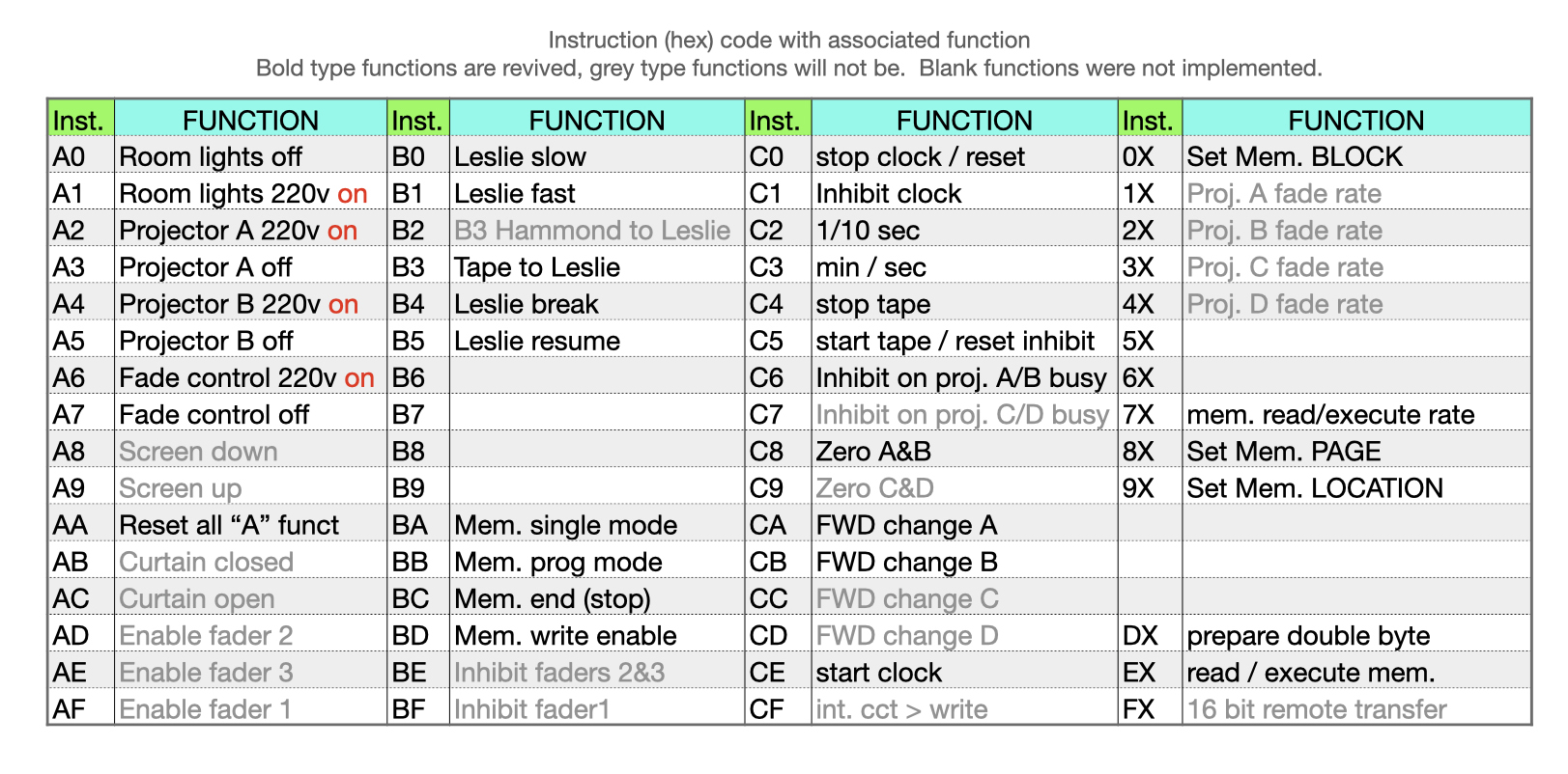
P82 has 55 assigned instruction codes, out of a total of 61:
A. 48 two-key (single byte) instruction codes defined, 5 not implemented – so 43 active.
B. 11 codes defined as operation/operand – 5 are implemented.
C. 2 “verb/noun” codes which invoke an additional cycle for operation with 16-bit word operands. One is DX for storing a full byte instruction into a designated memory location, the second is FX which initiates a 16-bit transfer to a remote smart controller which can interrupt the P82 and return 16-bits of data/status in return.
As well as instructions which can be executed manually or stored in memory, there are the transfer options to determine what will be written to, or read from, an audio device and in which format.

WRITE to TAPE — (1) byte transfer mode
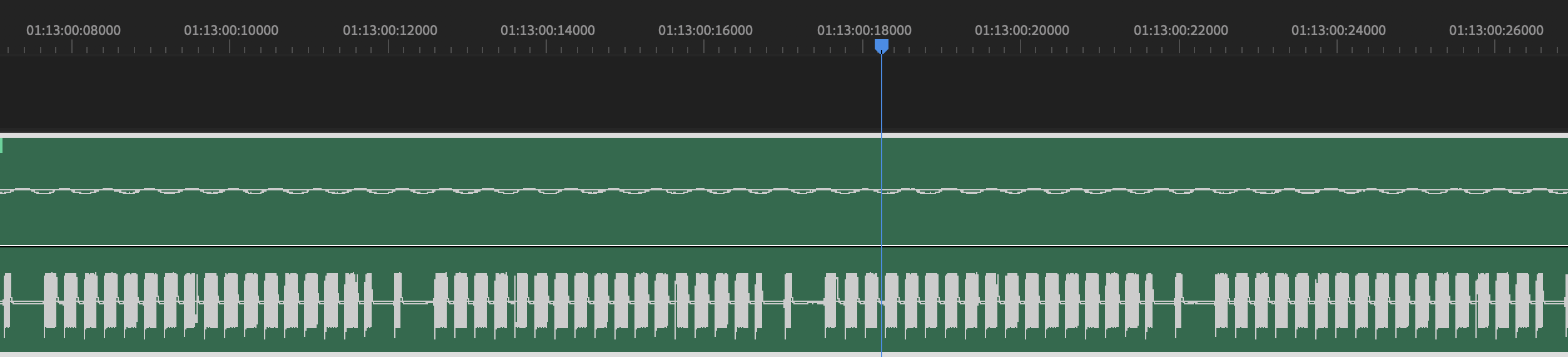
Next step here is to verify the “write to tape” functionality, much easier on a digital audio recorder than on the TEAC A-3440. And even easier to visualise and verify using Adobe premiere to display the final result. From the P82 keyboard we can select what we write to tape — or rather lets say write to our audio device, as our Zoom F8. Write selection options are: memory, keyboard, internal clock, remote status. For the test we choose clock and keyboard. We set the 1 second clock running and recording, then key in some more instructions over it. This first test is in write byte mode.
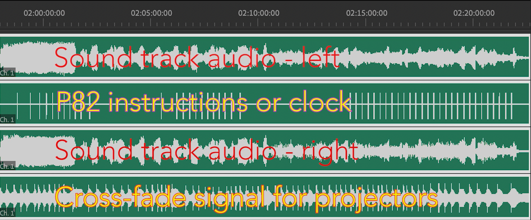
The two sources are correctly identified and recorded. Here we see the normal clock interval, plus one of the individual extra instructions inserted between them — kind of time sharing, handled by the P82 logic.

Zooming in we can make out the sync timing and 8-bits of information of each instruction – one byte instruction is ≈ 55ms. The oscillations are counted up against a down counter. Count greater than space equates as “zero”, and count less than space equates to a “one”. So just for fun we can even check the values visually, this example (bit zero first on the left) is 1101 0101 = Hex10, Hex11 = AB
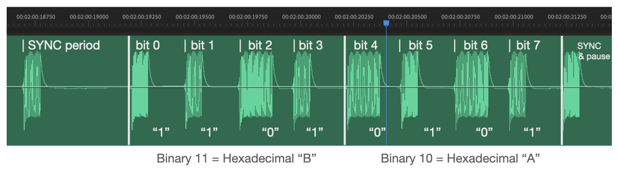
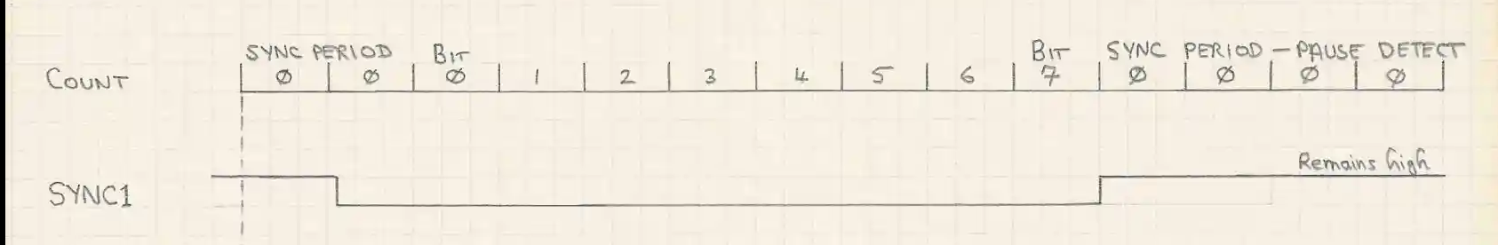
This concept of A-D and D-A conversion is very tolerant of tape speed changes and audio level settings. Timing comparisons are uniquely within the bit and it will work as long as most of the cycles are counted. P82 nevertheless has a visual set-up for levels, saturation, and threshold to accommodate different audio devices.
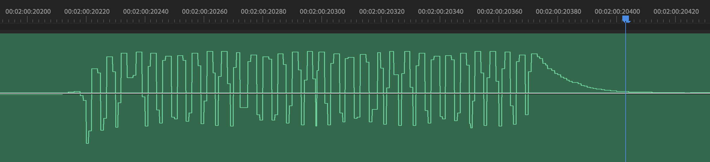
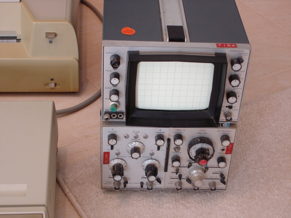
During construction in 1982 an oscilloscope was necessary to obtain such clarity; fortunately we had the HP 180A. Today Adobe Premiere does the job for us — display is set to time-units mode to see down to the individual cycle level of an audio waveform. Our waveform is using 48kHz, so there are 48000 time-units per second.
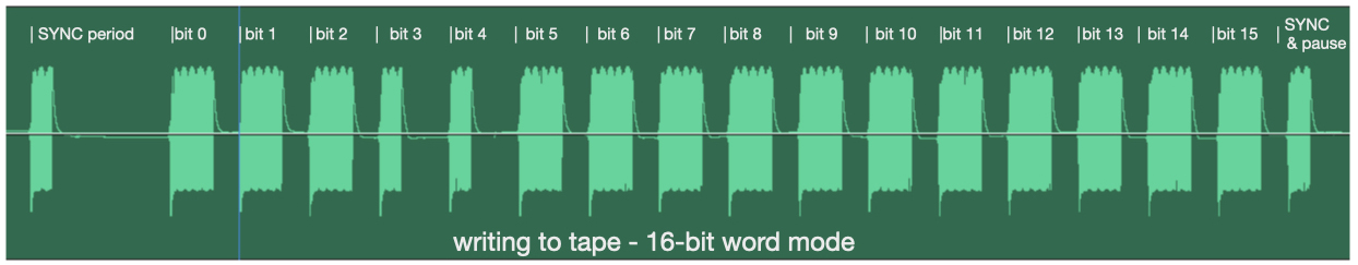
WRITE to TAPE — (2) word transfer mode
P82 keyboard instructions are all one byte (2 hexadecimal keys) and so writing in byte mode satisfies basic operation. However word mode (= double byte, 16 bits, or 4 hexadecimal digits) is required for the internal clock and for external date transfers and for use with the HP9825 — select the source we wish to write and “write word”. Byte and word modes should not be mixed.
Transferring memory data – display can show memory address, data, or both.
Index — P82: archive post — P82 build — revival(a) — revival(b) — revival(c) — remote (d)
